Same Computer A, but now it needs to talk to Computer C:
Computer A, MAC address aa:bb:cc:11:22:33, IP address 10.200.200.10/24
Computer C, MAC address ab:cd:ef:12:34:56, IP address 10.100.100.10/24
Computer A: *Hey, I need to send something to 10.100.100.10 but that DOESN’T look like it’s on the same network as me.*
As the great Tom Magliozzi of Car Talk1 once said, “how do it know?” The answer lies in the IP address and that “/24” at the end.
IP Addressing Basics
When you configure a computer with an IP, you give it an IP address, a subnet mask, and usually a default gateway. An IP address looks like 10.100.100.10. However, IP addresses are really Binary under the covers, and look like this:
00001010011001000110010000001010We can put the decimal points back in to help visualize how the format we’re familiar with (called dotted decimal notation) translates to the binary representation. We get 4 groups of 8 bits, called an octet, a term we will still use even when not using binary.
00001010.01100100.01100100.00001010An IP address has two sections. The first indicates the logical network it belongs to, and the second is its unique host number on that network. How can you tell which part is the network and which part is the host? We use the subnet mask, which is a number that tells you quickly where the host part begins and ends, and it does that by MASKING the network portion when comparing IPs. You may see subnet masks given in two forms: dotted decimal form like 255.255.255.0, or CIDR2 form (sometimes called slash notation) like /24, and they are the same thing. 255.255.255.0 is really:
11111111.11111111.11111111.00000000If you’re clever, you already see that’s 24 1’s. So /24 just means “the subnet mask is 24 1’s long. So, to find the network portion, you put them side by side, and any portion that is covered up by a 1 is the NETWORK portion of the address, and the remainder is the HOST.
00001010.01100100.01100100.00001010
11111111.11111111.11111111.00000000
[        NETWORK         ] [ HOST ]
To get the network address, set every bit that is not covered by the mask to 0, convert it back to decimal, and you get the network is 10.100.100.0 with a 24-bit mask, or 10.100.100.0/24. This works with any length of subnet mask.
There are some special IP addresses that one should know about: the network address and the broadcast address. The network address has a host portion of all zeros and is used in the routing process to identify the network itself. The broadcast address has a host portion of all ones and is used to send traffic to every address in the network. Broadcast packets are encapsulated in frames destined for the broadcast MAC. These addresses are reserved and cannot be assigned directly to a host3. For example, our 10.200.200.10/24 IP address can find the network broadcast addresses by setting the host portion to all zeros and all ones respectively:
IP Address - 10.100.100. 10 | 00001010.01100100.01100100.00001010 |
Routing Packets for Fun and Profit
When Computer A needs to send something to Computer C’s 10.100.100.10, it compares its IP address with the destination, and if the bits covered up by the subnet mask match, it is assumed they are on the same network. If they don’t, they aren’t. It sends the packet to its default gateway4. Computer A will instead send an ARP: “Hey, I need my default gateway, who has 10.200.200.1?”and assuming that’s the proper default gateway, 10.200.200.1 (which may be a firewall, a layer-3 switch, or a router) will reply with its MAC address, and 10.200.200.10 will encapsulate the packet in a frame and forward it. From there, 10.200.200.1 (the gateway) will decapsulate the frame, look at the packet, and see if it knows how to reach the destination address of 10.100.100.10 by looking at something called a routing table. If it knows a specific next hop address, it will ARP for the address (if it doesn’t already know the MAC), get a reply, and send it off. If it DOESN’T, 10.200.200.1 will send the packet to its own default gateway, and so on, and so on. Either way, the default gateway (and every other hop along the way) decapsulates and re-encapsulates the frame with a new source and destination MAC, but the same IP packet (and thus the same source and destination IP.) This is called routing.
Let’s talk about that routing table briefly. The routing table is a list of networks and the next-hop address (or interface) to send traffic destined for that network. Each of these mappings of a network to a next-hop is called a route. By default, the routing table simply contains information about locally connected networks, as that’s all the router knows about. We can also configure something called a static route, a manually configured mapping of network to next-hop. We’ve mentioned default gateways, and routers have those too. This is a route to take when there are no matching routes in the routing table. On a router, they are sometimes referred to as a default route or gateway of last resort.
Dynamic routing: Teamwork makes the dream work
We can also configure something called a routing protocol, which is a language that routers can speak to each other to share information from their routing tables. This allows for routers to automatically learn and ‘forget’ routes as changes are made elsewhere on the network. This sharing is called dynamic routing Within a network, common routing protocols include BGP, OSPF, and EIGRP (Cisco only). Between networks or companies, or out on the public internet, BGP is THE routing protocol. Each individual routing protocol has its own decision-making rules and processes, and the complexities and differences are beyond the scope of this material. The key takeaways are that the routing table exists, it is made up of mappings of destination networks to next-hop addresses called routes, and processes called routing protocols exist to allow routers to share routing table information with each other.
One thing to note: In many cases, routing is done by switches. Many switches are what is sometimes known as “layer-3 switches”, and have routing functionality as well as switching, allowing them to route traffic between VLANs without having to send the traffic to a different device. There are still dedicated “routers” that exist, often existing at the edge of the network to handle internet connections or WAN connections, but more often than not these days, routing is handled either on a layer-3 switch or within a firewall. More on firewalls later, by the way.
Better separation through VRFs
Before we dive a little deeper into BGP, There is one additional concept worth knowing about as we’re learning about routing, and that is the VRF (Virtual Routing and Forwarding)5. A VRF allows us to take a router and split it up into smaller virtual routers, each with their own interfaces, routing table and routing protocols. VRFs are, by design and default, isolated from each other. Any cross-VRF communication needs to be explicitly enabled by physically or logically connecting the VRFs together.
VRFs are commonly used by service providers to isolate individual clients from each other, and to keep their internal traffic isolated from clients. They are also commonly used by individual organizations to create security zones within their own networks. We will reintroduce the concept of VRFs later, but you should know they exist and that they will be very important as we proceed.
Border Gateway Protocol (BGP) – A Quick Primer
BGP is the routing protocol of the internet and has become the most common routing protocol on most WANs and in most modern datacenters. BGP is organized via a concept called Autonomous Systems (AS), each identified by an Autonomous System Numbers (ASN). ASNs come in public and private flavors, similar to IP addresses, and are assigned out by the same groups that assign IP addresses. ASNs were originally 16-bit and thus limited to the range 0-65535. In 2007, 32-bit ASNs were created, expanding the pool to 4,294,967,295 ASNs. The ranges 64512-65534 and 4200000000–4294967294 are reserved for private use.
There are two flavors of BGP. The first is iBGP, or Interior Border Gateway Protocol. This is used for exchanging routes within an AS. For example, our PERs would utilize iBGP to exchange routes with each other within AS 11320. The second is eBGP, or External Border Gateway Protocol (eBGP), which is to exchange routes between two different ASNs.
Two routers configured to exchange routes via BGP form a peering session, often called a neighbor relationship. A peering session is defined, at minimum, by the neighbor’s IP and ASN. A password can be used to ensure a misconfiguration doesn’t result in peering with an untrusted peer. Additional options can be set or changed on a per-peer basis, such as timer values.
Once the BGP session is negotiated, the keepalive and hold timers become active. The keepalive timer is typically 60 seconds, and the hold timer is typically 3 times as long, making the default keepalive of 60 seconds result in a hold time of 180 seconds. Once the session starts, the hold timer starts ticking up from 0. Keepalives are sent at the interval by the keepalive timer. Every successful keepalive restarts the hold timer. If the hold timer reaches the configured hold time, the routes learned from that neighbor are withdrawn.
The two routers also begin exchanging routes with each other, in a process called route advertisement. The routers are configured to select which routes from the route table to advertise to a neighbor. By default, any routes learned via BGP will be readvertised. Additional routes from other routing protocols can also be selected for redistribution. This can be done as broadly as “redistribute all connected routes” or “redistribute all static routes”. A BGP peering can also be configured with a feature called default originate. With this feature enabled, the BGP process will generate and advertise a default route back to itself. This route doesn’t need to already exist in the router table or BGP table.
If required, filtering of which routes will be re-advertised can be done through the use of prefix lists. Prefix lists are made of rules that are processed in order, like firewall rules. In a rule, you can specify a network, such as 192.168.0.0/24, and whether the rule applies to only that specific network (equal to, or EQ), that network and all larger network masks (greater-and-equal or GE, in this case, 24->32), or that network and all smaller network masks (lesser-and-equal or LE, in this case 24->0). You also choose whether the prefix list is going to PERMIT or DENY advertisement of matching routes. Any routes potentially selected for advertisement are compared against the rules in the prefix list. If a PERMIT is matched, the route is selected. If a DENY is matched, it is not. Every prefix list has a hidden deny at the end, also known as an implicit deny.
Another construct, known as a route map, can be used to add or change the information about one or more routes before advertising them. For example, a route map can be used to modify the next-hop address of a route or assign a route a higher weight to cause it to be more preferred over an identical route learned from another source.
Prefix lists and route maps can also be applied to routes that are learned, as a way of ensuring that a misconfiguration or malicious actor doesn’t advertise a route that causes an issue.
The BGP process chooses which routes learned to install in the actual route table. It can use different metrics, but the default and most commonly used is the AS Path Length. To explain this, let’s say there are 4 routers, AS1, AS2, AS3, and AS4, peered in a circular fashion. That is:
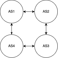
BGP is what is called a path vector protocol. That is, every route is advertised with information that indicates the “path” that route was originated and learned from. That is, when AS1 advertises a route to AS2, the route includes “AS1” in the path. When AS2 readvertises that route to AS3, the path now includes “AS1 AS2”. When AS3 readvertises it to AS4, it is now “AS1 AS2 AS3”.
So, in our example, AS2 will learn a route from AS3 twice: Once directly from AS3, and once via AS3-AS4-AS1. Out of these two, the one directly to AS3 is selected to be installed in the router table. However, if the link between AS2 and AS3 were to be cut and that direct route withdrawn, the alternate path via AS3-AS4-AS1 will be selected and installed.
Now, consider a route advertised from AS1 to AS2, then AS3, and then AS4. Were AS4 to readvertise that to AS1, we’d have a bit of a loop. Loops are bad! However, BGP is clever. AS1 will look at the AS path, see its own AS in the path, and understand “clearly I already know about this route, I will disregard this advertisement.” This particular feature, while generally very good and helpful, can sometimes cause problem when a route passes through two VRFs on the same router. As all VRFs on the same router generally share the same AS number, a route can be learned by a VRF that has its own AS in the path, having originated from another VRF on the same device. In circumstances where this is expected, and the risks and required careful planning are accepted, this check can be disabled.
There is a lot more to BGP, but this is a good foundation of what we need to know to understand BGP in NSX.
- If you have never heard of or listened to Car Talk, your life is incomplete. The wisdom of Click and Clack, the Tappet brothers, holds the keys to solving all of the world’s problems. I think. ↩︎
- CIDR – Classless Inter-Domain Routing. This is a holdover term from a long-forgotten age. Addresses USED to be “classful”, that is, either class A (leading bit 0, 8-bit long network address), class B (leading bits 10, 16-bit long network address), class C (leading bits 110, 24-bit long network address), class D (leading bits 1110, 4-bit long network address, reserved for multicast), or Class E (leading bits 1111, network bits not defined.) The only size networks allowed were /8, /16, and /24, with /4 multicast spaces. This was greatly limiting and was causing IP address exhaustion much quicker than anticipated. To resolve this, classless networking was developed to allow for variable-length network masks. These smaller networks, or subnets, give us much more flexibility in how we design networks. ↩︎
- Two exceptions: NAT and point-to-point (/31) networks allow you to use the network and broadcast addresses in very specific scenarios. ↩︎
- Usually, at least. We’ll talk about routing tables and static routes later; computers have their own routing tables as well. This allows computers to have multiple network interfaces and make decisions on how to route traffic between them. Don’t worry about this, though. It’s quite rare these days for a server to have/need multiple NICs. ↩︎
- Whether or not you are intended to pronounce this as initials, “V-R-F”, or as a word, “Virf”, is a debate that has been raging since ancient times. This disagreement has torn apart families and sundered societies and is best left to philosophers and academics. This is an accepting space, and both pronunciations are allowed here. ↩︎
