
Management & Control Plane
Management Plane
The management plane is responsible for receiving, maintaining, and distributing configuration throughout the NSX environment. To this end, the main functions of the NSX management plane service include:
- Providing the user interface and API access for creating, configuring, and monitoring other NSX components, and interfacing with vCenter to create networks/VMs for the NSX components.
- Storing desired configuration in its database and pushing configuration to the control plane to make it active.
- Installs kernel modules on participating hypervisors to allow for kernel-level processes such as distributed routing and distributed firewall.
Control Plane
The control plane is responsible for determining and distributing the active state of the system based on configuration received from the control plane. There are two main components to the control plane:
Central Control Plane (CCP)
Implemented as a cluster of three nodes, the CCP is responsible for receiving and calculating the active configuration based on the data stored in and received from the Management Plane and distributing it to the Local Control Planes (LCPs) on the individual nodes in the environment.
Local Control Plane (LCP)
The LCP runs on individual nodes and is directly adjacent to the data plane it controls. It is responsible for programming the forwarding entries and firewall rules of the data plane.
NSX Manager Appliances
The NSX Manager Appliances handle the Management and Central Control Plane functions for the NSX environment. There must always be a cluster of three NSX Manager Appliances for environment stability. This rule of three allows the cluster to always be able to break a tie when there is a disagreement between nodes over the active configuration, either due to a disruption in connectivity or an appliance being rebooted for patching or otherwise. Care must be taken to appropriately distribute the appliances to ensure that two appliances are always online. The Managers maintain all configuration in-memory immediately as well as written to disk and synchronize this configuration between the cluster. Each manager as a dedicated IP, and the environment can be managed directly through any of the three or via a load balancer. Alternatively, a virtual IP address can be configured, and one node will be ‘elected’ to own the virtual IP and handle all incoming connections.
The Manager Appliances are where all aspects of the environment are configured, and where that configuration is maintained. They also maintain a database of network segments, VMs, and Hosts and their current state/location. It is important to note that, as a control plane, traffic does not pass through the NSX Manager Appliances. The Control Plane service is, however, responsible for providing state and configuration information to the local control planes throughout the environment.
The loss of a single (or even two) NSX Manager Appliances should not be service impacting if all else is well. However, on a very bad day, if all NSX Manager Appliances are down, with nothing to maintain state and configuration, things quickly go bad. VMs that are vMotioned can no longer be found, as nothing is tracking them within the software defined network, and one device wishing to send traffic to another will not be able to find out where to send it.
Data Plane
The data plane is responsible for handling traffic based on tables populated by the control plane. It also reports topology to the control plane and maintains packet-level statistics. The individual hosts running the local control plane services and the forwarding engines are called transport nodes. Transport nodes run an instance of the NSX Virtual Distributed Switch, or N-VDS. On ESXI, the N-VDS is built on top of the vSphere Distributed Switch. This becomes apparent when you see that network segments created in NSX result in port groups being created in vCenter.
As illustrated above, there are two main types of transport nodes in NSX:
- Hypervisor Transport Nodes are hypervisors prepared and configured for NSX, enabling NSX to provide network services to the VMs running on the node. By definition, a transport node implements the NSX data plane for consumption by VMs.
- Edge Nodes are “service appliances dedicated to running centralized network services that cannot be distributed to the hypervisors.” (“Create an NSX Edge Transport Node – VMware Docs”) Edge nodes can either run on bare metal or as virtual machines. They are grouped into clusters, each cluster representing a pool of capacity. Note that there is no “Edge Node” service, but that multiple services consume the resources of the edge nodes.
NSX Logical Switching
One of the key roles of NSX is the creation of virtual layer 2 networks, called Segments. Remember that a layer 2 segment is a logical division of a network, and that all endpoints within a layer 2 segment can be thought of as directly adjacent to each other.
NSX Virtual Switch
A transport node implements the NSX data plane through the use of a virtual switch. As we mentioned earlier, a virtual switch is exactly what it says: a virtual representation of a switch, with virtual switch ports, and the ability for those virtual switch ports to be logically segmented via layer 2 constructs such as VLANs. The virtual switch also enables traffic to be forwarded to physical interfaces that participate in the virtual switch. We also talked about a distributed virtual switch, which is a virtual switch that spans multiple hypervisors. NSX adds additional capabilities to the standard DVS.
Segments
A segment is, as stated, a virtual layer 2 network on the NSX Virtual Switch. There are two types of segments, but before we define them, lets define some terms to help us understand them better:
With those terms defined, let’s talk about the two types of segments in NSX:
- VLAN-Backed Segments are segments that are tied to a VLAN, which allows that segment to extend beyond the NSX/VMWare infrastructure. This requires that the VLAN backing the segment be configured on the physical switching infrastructure in order for VMs participating in a VLAN-backed segment on different transport nodes to communicate.
- Overlay-backed Segments are segments that are backed by a virtual network. Traffic between VMs on the same overlay-backed segment will be carried via the already-configured overlay tunnel between transport nodes, and the creation of additional overlay-backed segments do NOT require changes to the underlying physical network.
Transport Zones
Transport zones are organizational units that designate the boundaries of a segments. A transport zone defines which segments are extended to which transport nodes. Transport zones are also either VLAN- or Overlay-backed. A segment created in a transport zone will share the same backing type as the zone. Only the nodes participating in a given transport zone will be able to see and participate in the segments for those transport zones.
Logical Switching & VLAN-Backed Segments
VLAN-backed segments function essentially the same as they do without NSX, and do not require any special consideration as far as how traffic is processed. NSX-managed VLAN-backed segments are created as port groups, but they are marked with a special icon that indicates they are NSX-managed. Once they are connected to VMs, the traffic is handled the same way as a traditional port group or distributed port group.
Logical Switching & Overlay Segments

Overlay Segments fully rely on the NSX control and data planes to function. Below is a diagram, once again from the NSX Reference Design Guide, that shows how the logical Overlay Segment and the physical infrastructure interact.
The upper part of the diagram shows a logical view of the segment as far as the VMs themselves are aware: a single layer-2 segment with 9 VMs connected, and everything behaves the same as if it were on traditional networking. The physical view in the lower portion reveals the added complexity that NSX is abstracting away for us: the 9 VMs are each running on different hypervisors that are, in fact, not even in the same rack or plugged in to the same switches.
To facilitate this, each hypervisor, being an NSX transport node, is configured as a TEP. Each TEP is configured with an IP address, and the physical network infrastructure needs to be configured to ensure that each TEP can communicate with each other. The TEPs do not need to be in the same subnet. The only requirement is that the latency between nodes and between any given node and the NSX Manager cluster be kept under 150ms. (In networking, 150ms is A Very Long Time, and this allows for NSX overlay segments to be extended over WAN links. Because of this, there are additional things happening behind the scenes to enable this flexibility.
Broadcast, Unknown Unicast, and Multicast Traffic Handling
The first consideration is in how broadcast, unknown unicast, and multicast traffic, sometimes referred to as BUM traffic, is handled. In our case, the most important type of BUM traffic is an ARP “who has this IP” broadcast. There are two main ways for this traffic to be handled, and we will use the example of VM1 originating a broadcast frame to explain them. The first is called “Head-End Replication Mode” and is shown below in a diagram from the NSX Design Reference Guide.
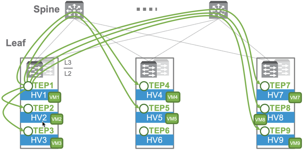
In Head-End mode, the TEP at the “head end”, or where the frame originates, will send a copy directly to the other TEPs. Note that a frame does NOT need to be sent to TEP6/HV6, as there is no VM on the segment there. This requires that the same data be sent 7 times, and this could be problematic for instances where bandwidth between the TEPs is at a premium.
The alternative is called “Two-Tier Hierarchical Mode” and is shown below, again from the NSX Reference Design Guide.

In this mode, we’re adding some additional information to the diagram: the IP addresses of the TEPs. In this design, TEPs in each rack are in distinct subnets, and TEPs are grouped in NSX by their subnet. In this mode, the following occurs:
- HV1 sends a copy of the frame to the other nodes in the same group.
- HV1 sends a copy to a member of both the second and third groups.
- The recipient of the copy in the second or third groups sends a copy to the other members of their groups.
This results in 7 copies being sent still. However, only 2 of those copies traverse the uplinks, reducing the bandwidth requirements on the uplinks. This multi-step process has a tradeoff for the reduced uplink bandwidth, as it will introduce a non-zero amount of latency to the process.
Unicast Traffic
It is desirable for flood traffic to be kept to a minimum. We talked earlier about how switches implement a MAC address table that associates MAC addresses to physical ports to minimize flooding. When a frame is destined to a known MAC, it is only forwarded by the switch to the corresponding port. By observing traffic and seeing where traffic from a particular MAC originates, the switch will ‘learn’ a MAC and populate the MAC address table with the MAC and its corresponding switch port.
NSX does the same, but in addition to mapping MACs to virtual switchports, it also maps MACs of remote VMs to their associated TEP. When a server needs to forward a frame to a remote host, this table allows the TEP to know where to direct it without having to further flood the network. These tables are populated by two methods: data plane learning and control plane learning. Data plane learning is fundamentally the same as how a physical switch works. By observing traffic, the nodes can see which virtual switchports or TEPs they receive traffic from MACs on and build the table. The nodes also share their tables with the NSX Controller. In addition, when a vNIC is attached to an overlay segment, the NSX Controller is notified of the MAC address and the TEP where the MAC is reachable.
The Controller maintains two central repositories to enhance the traffic processing of the system:
- A Global MAC table that maps MACs to TEP IPs.
- A Global ARP table that maps MACs to IP addresses.
The global MAC table proactively populates the nodes so they don’t need to learn MACs. If a node DOES receive a frame destined for an unknown MAC address, it first checks with the NSX Controller to see if the information is in the global table. If it is, it learns the entry and no flooding is needed.
The Controller also maintains an ARP table to facilitate ARP suppression. The NSX virtual switch “snoops” DHCP and ARP traffic to lean MAC to IP associations and reports those associations to the NSX controller. It is then able to use that information to respond to ARP requests without needing to flood the segment with the ARP broadcast.
NSX Logical Routing
NSX also handles routing of traffic between layer 2 segments. Without NSX, east-west traffic that needs to route between two network segments, even between two VMs on the same hypervisor, would need to leave the hypervisor, travel to a layer 3 device, be routed, and travel back to the hypervisor. NSX eliminates that extra travel by performing the routing functions locally on the hypervisor using a process called distributed routing which handles east/west traffic. NSX is also able to facilitate routing-adjacent services such as connectivity to physical networking, static/dynamic routing, firewalling, NAT, VPNs, and DHCP. These services run on one or more NSX Gateways. There are two main designs that can be used in an NSX deployment: Single-Tier & Two-Tier.
Single Tier Routing
The first is what is called “single tier”. In “single tier”, there is a single Gateway that handles both North/South traffic and East/West traffic, as well as any additional services required such as routing, NAT, firewalling, DHCP, or VPNs. This is called a Tier-0 Gateway, often referred to as simply a T0. The T0 gateway has two components: a distributed router and a centralized services router. These are often referred to as a DR and an SR.
Distributed Router
The DR is essentially a router with interfaces connected to multiple networks/subnets. From a traffic-handling perspective, it functions the same as a physical router would in traditional networking: a packet is received on one interface and routed to another based on the routing table. It is the distributed nature that makes it special. It runs in kernel modules on every transport node, and through this, every hypervisor is able to make routing decisions and act as the gateway for every network. That is, say we have two networks: a Web network, 172.16.10.0/24, and an App network, 172.16.20.0/24, with each network’s gateway being the first address in the subnet. On a traditional network, Any traffic between these two subnets, even between hosts on the same hypervisor, would need to traverse to a physical router to be processed. In NSX, every hypervisor can act as the default gateway and make routing decisions. Like traditional routing, this process is stateless, meaning each packet is routed without considering the packets that came before. A key rule to understand is that routing always happens closest to the source. That is, you will see that traffic will be routed by the hypervisor hosting the VM that is the source of the traffic. The diagram below demonstrates this rule being applied to east-west routing.

Traffic between VMs, whether they be on a single hypervisor, such as the flow in purple from Web1 to App1, or on two different hypervisors, such as the flow in orange from App2 to Web1, are processed by the distributed router process on the local hypervisor. In the case of the flow in orange, once the traffic is routed to the web segment, the logical switching process takes over, forwarding the traffic to the TEP on HV01 and on to Web1.
Services Router
Distributed routing is what is known as stateless. That is, each packet is routed independently. There is no tracking of conversations or flows that needs to be shared between transport nodes, allowing each node’s distributed router process to handle traffic as quickly as possible. North/South routing generally requires state to be tracked or relies on stateful or location-bound services to function. These include, but are not limited to:
- Physical infrastructure connectivity via static/BGP/OSPF routing
- NAT
- VPN
- Stateful Perimeter Firewalling
- Bridging
- Service Interfaces
Whenever a service is enabled that cannot be distributed, a Services Router (SR) is created on an edge cluster. Remember that edge clusters are made up of edge nodes and provide centralized resources enabling these services to run in a highly available and scaled out fashion.
The following diagram from the NSX architecture guide demonstrates how the DR and SR components can be visualized as two parts of a single logical construct.

Looking at this logically, we see the logical construct of the Tier-0 Gateway, comprised of both the distributed and services components, contains the uplink to the physical infrastructure and acts as the default gateway for the VM networks. When we break it out into its physical components, we see a clearer picture of how this works. The Distributed components exist on all of the transport nodes (the hypervisors where the VMs live), as well as the edge node. The Services component exists solely on an edge node and provides the uplink to the physical routing via an external segment. An intra-tier transit link is automatically created to connect the services and distributed components. By default, this intra-tier transit link uses 169.254.0.0/24 addresses.
Putting It Together
A DR and SR work together to form a logical Tier-0 Gateway. Let’s put the east-west functionality of the DR and the north-south functionality of the SR together. Below is a sample packet walk for traffic from Web1 out to the physical infrastructure taken from the NSX Reference Design Guide.
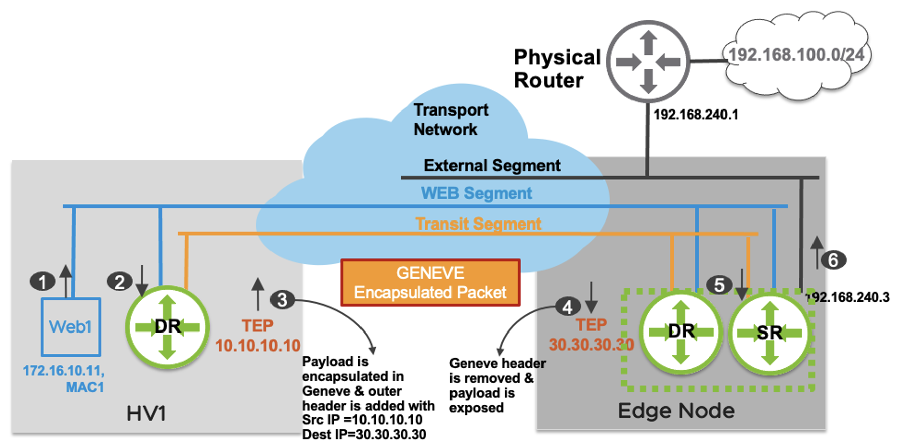
- Web1 (172.16.10.11) wishes to send a packet to a host on the physical infrastructure, 192.168.100.10. As this host is not on the local network, Web1 forwards the packet to the default gateway on the local distributed router (172.16.10.1).
- The packet is received on the local DR. DR doesn’t have a specific connected route for 192.168.100.0/24 prefix. The DR has a default route with the next hop as its corresponding to the SR’s interface on the Transit Segment, which is hosted on the Edge node.
- Traffic from node to node needs to be encapsulated in order to be sent and received while retaining the original packet data. The HV1 TEP encapsulates the original packet and sends it to the Edge node TEP with a source IP address of 10.10.10.10 and destination IP address of 30.30.30.30.
- The Edge node is also a transport node. It will encapsulate/decapsulate the traffic sent to or received from compute hypervisors. The Edge node TEP decapsulates the packet, removing the outer header prior to sending it to the SR.
- The SR performs a routing lookup and determines that the route 192.168.100.0/24 is learned via external interface with a next hop IP address 192.168.240.1.
- The packet is sent on the VLAN segment to the physical router and is finally delivered to 192.168.100.10.
Now, let’s look at the reverse traffic packet walk for the reply, also from the NSX Reference Design Guide.

- The external device (192.168.100.10) replies with a packet to “Web1” (172.16.10.11). The packet is routed by the physical router and sent to the external interface of Tier-0 Gateway hosted on Edge node.
- A single routing lookup happens on the Tier-0 Gateway SR which determines that 172.16.10.0/24 is a directly connected subnet on “LIF11”. A lookup is performed in the “LIF1” ARP table to determine the MAC address associated with the IP address for “Web1”. This destination MAC “MAC1” is learned via the remote TEP (10.10.10.10), which is the “HV1” host where “Web1” is located.
- The Edge TEP encapsulates the original packet and sends it to the remote TEP with an outer packet source IP address of 30.30.30.30 and destination IP address of 10.10.10.10. The destination VNI in this Geneve encapsulated packet is of “Web Segment”.
- The HV1 host decapsulates the packet and removes the outer header upon receiving the packet. An L2 lookup is performed in the local MAC table associated with “LIF1”.
- The packet is delivered to Web1.
The SR is also where any stateful services such as NAT and stateful firewalling would happen. In the example above, if Web1 were trying to reach an internet host, NAT would happen on the SR.
Two-Tier Routing
Single tier routing works very well for organizations requiring a single network space without environment isolation. However, when isolation is needed either between business units or in a multi-tenant environment, we have the option of Two-Tier Routing. Two-Tier routing introduces an additional gateway referred to as a Tier-1 Gateway. Multiple Tier-1 Gateways can share a single Tier-0 gateway. The Tier-0 provides north-south connectivity for all child T1s, bridging the physical infrastructure with the Tier-1 Gateways. The diagram below shows two tenants, Blue and Orange, with their distinct Tier-1 Gateways and a shared Tier-0 gateway.
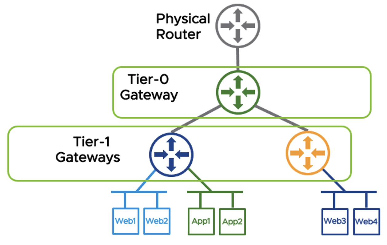
Tier-1s are also comprised of DR and SR components. Services such as NAT, VPN, and Gateway Firewalling are handled by the Tier-1 SR, whereas east-west routing are handled by the Tier-1 DR. The Tier-0 can route public IPs to the Tier-1s, allowing tenant-specific NAT and firewalling to be configured on the Tier-1, and for the Tier-1s to initiate tenant-specific VPN tunnels. Tier-0s can also be used to route traffic between Tier-1s.
In this scenario, east/west traffic for the Blue tenant is handled by the Blue Tier-1’s DR. North/South traffic would route through the Blue Tier-1’s SR to the Shared Tier-0’s SR, and out through the Shared Tier-0’s external network.
Tier-1s can leverage a service interface to connect directly to network infrastructure as needed without needing to pass through the T0.
One thing to note is that, in this design, there is no way to place a device between the Tier-0 and Tier-1. The Tier-0 is the upstream provider for the Tier-1. As such, there is no clean way to deploy a discrete firewall for just a single Tier-1. The Tier-0 and everything upstream of the Tier-0 are shared by all Tier-1s. This presents challenges to the service provider model for multi-tenant deployments where a service provider or IT organization might want to allow for certain T1s to have different external networking. This can either be accomplished by building distinct T0s, or by leveraging a concept called T0-VRFs. In most private deployments, however, perimeter firewalling can be slotted in front of the T0 with no problem.
Tier-0 VRFs
Starting in NSX-T 3.x, the option to subdivide a Tier-0 into VRFs allowed for much greater flexibility in the provider model for multi-tenant networking. For tenants that wish to rely on the provider for perimeter services such as NAT and Firewall, the traditional Tier-0 model can continue to be used. For tenants requiring the additional flexibility, a Tier-0 can be deployed and carved into Tier-0 VRFs, which are able to then act as provider T0s for tenant T1s. There are some restrictions about what can be configured in a T0-VRF, and what is inherited from the parent T0.
T0-VRFs inherit the following from parent T0 and cannot be changed:
- Hosting edge cluster
- HA Mode (A/A v. A/P)
- BGP Local ASN
- Intra-Tier Transit Subnet (DR<->SR)
- T0/T1 Transit Subnet
The following can be changed:
- Interface networks & IPs
- BGP Neighbors
- Prefix Lists, Route maps, Redistribution Rules
- Firewall Rules
- NAT Rules
Routing Capabilities
NSX supports static and dynamic routing protocols. T0s can be configured with static and dynamic routing, whereas T1s exclusively use static routing.
Tier-0 Gateways
In many cases, a T0s can be configured with a single static default route towards the upstream physical router. Additional static routes, either to address on the external network, to specific T1s, devices reachable via a service interface, or otherwise. It’s also possible for T0s to be configured with multiple external networks for redundancy, allowing for multiple default routes to be configured. Equal-Cost Multi-Path (ECMP) can be leveraged to increase available bandwidth and provide fault tolerance via load balancing. ECMP uses a process called “hashing” to ensure that traffic from a particular flow (conversation between two devices) remains on a single path. It is further recommended that Bidirectional Forwarding Detection (BFD) be configured to detect when a particular path should be considered down and removed from consideration. In cases when BFD is not available, a VIP can be utilized to provide high availability. VIPs are less reliable and slower than BFD and cannot provide ECMP. Therefore, they can only be utilized when the HA strategy is Active/Standby and should only be used when BFD is unavailable.
T0s can also be configured to use OSPFv2 and BGP. This material will not cover OSPF, as quite frankly, I’m not particularly strong on the topic, and I don’t see very much OSPF in the wild. I think I have had one client using OSPF in the past 10 years. The NSX Design Reference Guide goes in depth on how OSPF would be configured, if you are interested in learning further. BGP configuration is the same as it would be on a physical router, the basics of which are covered earlier in this series. BGP, being a stateful service, runs on the services router. BGP also utilized ECMP for load balancing across redundant paths, as well as BFD to quickly determine path faults. BGP and static routing can be configured within a T0-VRF the same as it would be on a standard T0, with the notable exception that a T0-VRF must share the local ASN with their parent T0.
Tier-1 Gateways
T1s utilize static routing exclusively. When T1s are provisioned, they are connected to their Provider T0 via a RouterLink segment. The RouterLink segments, by default, utilize 100.64.0.0/162. A default static route pointing to the T0 Gateway’s DR RouterLink port is automatically installed in the T1’s routing table. Additional static routes can be configured to point to a device reachable via a service interface or other layer-3 reachable address.
Route Types & Route Advertisement on NSX Gateways
Tier-0 Gateways have the following route types:
- Static – User configured static routes
- NAT IP – NAT IP addresses discovered via NAT rules configured on the T0.
- BGP – Routes learned via BGP Neighbors
- IPSEC Local IP – Local IPSEC Endpoint IP addresses used for establishing VPN sessions.
- DNS Forwarder IP – Listener IP for DNS Queries from clients. Also used as the source IP for forwarding DNS requests to a DNS server
- Inter-SR – SRs of the same T0 gateway in the same edge cluster will create an automatic iBGP adjacency between them to exchange routing information, allowing for Active/Active configurations.
Tier-1 Gateways have the following route types:
- Static – User configured Static routes
- Connected – Routes for connected subnets
- LB VIP IP – IP address for a load balancing virtual server.
- LB SNAT – IP address or range of addresses used for Source NAT by load balancer.
- IPSEC Local IP – Local IPSEC Endpoint IP addresses used for establishing VPN sessions.
- DNS Forwarder IP – Listener IP for DNS Queries from clients. Also used as the source IP for forwarding DNS requests to a DNS server
There is no traditional dynamic routing between T0 and T1 gateways. NSX automatically handles the creation of routes to facilitate the traffic between a T0s and T1s. That is, while the Tier-0 and Tier-1 are not running a traditional routing protocol between them, such as BGP, route types can be selected and filtered for redistribution, and NSX will handle installing the appropriate routes. This is a bit of a difference without a difference, but it is worth noting. Policies can be set to determine what routes are advertised from a T1 to a parent T0. A T1 that is hosting an isolated network space might be set to only advertise IPs used for NATs, whereas an organization using T1s for business unit separation might choose to advertise all the locally connected networks, allowing them to be reachable by other T1s or external sources.
NAT Capabilities
NAT can be enabled on both Tier-0 and Tier-1 Gateways. Tenant NATs would be configured on the Tier-1. Source (SNAT), Destination (DNAT), and Reflexive (Bidirectional or Static) NATs can be configured, as well as No-SNAT and No-DNAT.
DHCP & DNS Capabilities
NSX Gateways can also provide DHCP and DNS services. For DHCP, NSX Gateways can either act as a DHCP relay, forwarding DHCP requests to a DHCP server, or as a DHCP server itself for NSX-managed subnets. For DNS, an NSX Gateway can act as a DNS Forwarder, including per-FQDN conditional forwarding.
NSX Security
We’ve already discussed how NSX acts as a switch and router. However, security is a core use-case of the NSX platform. In fact, many organizations that will not be using NSX Overlay Networking will still implement NSX specifically for the security functionality, as NSX Distributed Firewalling (DFW) enables micro-segmentation at the hypervisor level even for VLAN-backed networking, without requiring any software or service to run within the guest VM OS. In addition to the Distributed Firewall, NSX offers the Gateway Firewall on the T0 and T1 logical routers to provide north-south firewalling at the perimeter of the tenant or NSX environment.
The Distributed Firewall and Gateway Firewall are configured in similar ways, as sets of individual rules processed in a top-down manner. Sources and destinations can be configured with either IP network statements or logical and grouping constructs, including statically and dynamically defined groups. They both allow traditional definition of source and destination port and protocol, but also allow definition of Applications, or named groups of port/protocol. There are many pre-defined Applications available as well.
They both also allow the filtering at Layer 7 by way of Network Context Profiles. Network Context Profiles utilize pre-defined signatures called AppIDs that can classify the actual application beyond just port and protocol. For instance, a traditional layer-4 firewall rule using port & protocol might define traffic to a web server as TCP-443, but there is no guarantee that the traffic being allowed is properly formatted SSL traffic. A Network Context Profile specifying the SSL AppID can be added to further inspect beyond port and protocol, verifying that the packets are properly crafted SSL packets, adding an additional layer of security. VMWare publishes the list of pre-defined AppIDs that make up Context Profiles, but they are also visible in NSX Manager.
Dynamic groups are a powerful construct that allows for automatic inclusion of VMs based on different criteria. The criteria include matching on the VM name (such as a group called Domain Controllers that includes any server with ‘DC’ in the name), VM OS (such as a group called Windows Servers that matches any VM reporting a Windows OS), or VM Tag. Security Tags allow you to tag a VM with a label, such as identifying all VMs in a particular application or departmental ownership. By using Dynamic Groups in your firewall rules, you can ensure that newly-created VMs are automatically protected by the appropriate firewall rules, reducing the risk of human error leaving a VM exposed to unwanted traffic.
NSX Distributed Firewall
The distributed firewall (DFW) is a kernel module allowing for stateful firewalling functionality to be distributed across the entire compute stack. The DFW acts at the vNIC level, enabling traffic to be filtered by the hypervisor. This prevents both unwanted inbound traffic that wasn’t already filtered by a perimeter firewall, but also can filter unwanted outbound traffic at the source, reducing bandwidth consumption and perimeter firewall resource requirements. Most importantly, it filters east/west traffic, even within a segment, due to its placement at the vNIC level.
DFW rules, once configured on the NSX Manager, are pushed to the Central Control Plane and distributed to the Local Control Planes on each transport node. Once an LCP receives the ruleset, it processes the rules and publishes them to vNICs. For greatest efficiency, only the rules relevant to a given vNIC are programmed on that vNIC, eliminating wasted resources comparing traffic to irrelevant rules.
It is important to understand that NSX is inherently single-tenant, even in situations with multiple T0s and/or T1s. As such, within NSX, there is a single Distributed Firewall with a single rule set broken into categories with purposes that make the most sense from a single tenant perspective. These categories are:
- Ethernet – Layer-2 rules can be placed here.
- Emergency – Temporary firewall rules for emergency occasions, for example, rules that would be turned on as part of a breach incident response plan.
- Infrastructure – These rules are intended to provide access to shared infrastructure services such as Active Directory, DNS, DHCP, NTP, Backup platforms, and management access.
- Environment – These would be rules between zones (Prod vs. Dev, PCI vs. NonPCI, etc.) or business units.
- Application – These would be rules between specific applications, application tiers, etc.
The Distributed Firewall processes each category in order, and within each category the rules are processed top-down. Within each category, rules can be broken up into sections for logical organization. Rules are given a context in which to apply, either to the entire DFW, or to groups of objects.
Within the Application section, the Distributed Firewall has a “Default Layer3 Section” that applies to the entire NSX infrastructure, even in a multi-tenant environment. Within the Default Layer3 Section is the Default Layer3 Rule. The default within NSX is to have this rule set to Allow at deployment time in order to ensure that development of and migration to a Microsegmentation-style security posture. The NSX recommendation is for that rule to be switched to Deny on once a proper rule set has been tested and established.
NSX Gateway Firewall
NSX Gateway Firewall can be enabled on T0s and T1s. The NSX Gateway Firewall is intended to act as a perimeter (or north/south) firewall, either by itself or in conjunction with an external firewall. As opposed to the DFW, which exists as a singular entity at the NSX level, Gateway Firewall acts at the level of the T0 or T1 it is a part of, and is configured independently.
The Gateway Firewall also has a Default Allow rule. However, this is set at the individual gateway level and can be changed per-gateway.
Firewall Rule Considerations
One of the guiding rules for policing traffic is to place policies as close to the source as possible. When planning security policies, I recommend having a diagram of your network on hand, allowing you to visually trace the traffic and identify the enforcement point nearest to the source.
Consider a two-tier deployment, with a perimeter firewall providing external networking to a T0 and its child T1s. Inbound traffic from the internet should be policed at the perimeter firewall, minimizing unnecessary traffic from hitting the T0 at all. Outbound traffic, however, should be policed as close to the source as possible, ideally leveraging the distributed firewall to police this traffic as close to the source as possible. In fact, due to the distributed routing nature of this traffic, as all E/W traffic between segments on the same T0 or T1 is handled within the Distributed Router, it never passes through the Services Router component, and therefore is not subject to rules on the Gateway Firewall. Those E/W rules are must be placed on the Distributed Firewall where they can act at the vNIC level.
It is also important, when implementing the NSX Distributed Firewall, to consider traffic that originated from external sources. Once the Distributed Firewall is enabled, all traffic is inspected. Therefore, once a DFW policy ruleset is in place, with a Deny All at the end of the ruleset, even inbound and outbound traffic becomes subject to the DFW and must be addressed. As such, one way to handle this is to assume that the perimeter firewall has done its job and to create an “Inbound” rule that allows all traffic that originated from outside NSX under the premise that the perimeter firewall has allowed it so it should be trusted. A matching “Outbound” rule that allows all traffic leaving NSX can be configured as well.
It is also important to remember that, since the DFW is intended to implement microsegmentation, meaning traffic is processed at the vNIC level, even traffic within a segment must be explicitly allowed if desired. That is, with traditional firewalling, 192.168.1.10 and 192.168.1.11, if adjacent, would be able to speak freely. With the DFW in place, even that same segment traffic will be filtered if not explicitly allowed. As such, a trusted network where all hosts can communicate can be defined with a rule that specifies the segment as the source and destination.
- LIF – Logical Interface, that is, an interface that doesn’t correspond to a physical port. Analogous to SVI being Switched Virtual Interface on a Cisco device. ↩︎
- 100.64.0.0/10 is an address space reserved via RFC 6598, “IANA-Reserved IPv4 Prefix for Shared Address Space”. Commonly referred to as the Carrier Grade (CG) NAT space, it is a shared, private address space intended to be used by service providers to provide connectivity between provider upstream devices and individual client network devices. For example, your ISP may use CG-NAT between their head-end and your cable modem. ↩︎
