Material potentially out of date!
Hey, it’s me writing on September 5th, 2025. I need to update this with the latest and greatest, and also with new knowledge I have from additional experience. So, please be aware that some material in here is no longer accurate. I’ll work on updating this soon !
Flow Virtual Networking is the network virtualization stack for a Nutanix AHV deployment. As of November 2024 when this was written, per the Nutanix Cloud Platform Software Options page on Nutanix.com, Flow Virtual Networking is included in both the NCI-Pro and NCI-Ultimate licensing levels.
Management & Control Plane
Management Plane
The management plane is responsible for receiving, maintaining, and distributing configuration throughout the Flow environment. To this end, the main functions of the Flow management plane service include:
- Providing the user interface and API access for creating, configuring, and monitoring Flow components, and interfacing with the AHV cluster to create networks/VMs for the Flow components.
- Storing desired configuration in its database and pushing configuration to the control plane to make it active.
Control Plane
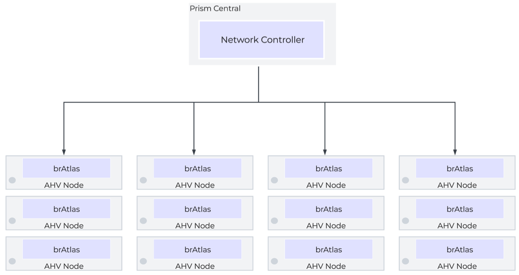
The control plane is responsible for determining and distributing the active state of the system based on configuration received from the control plane. The Flow control plane runs via the Network Controller, a containerized service that runs within Prism Central’s microservices infrastructure. The Network Controller service is internally referred to as Atlas. The Network Controller leverages Open Virtual Network, which builds on OVS to enable layer-3 functionality.
Prism Central
The Prism Central VMs directly handle the management plane functions for the Flow environment, and they host the control plane in the form of the Network Controller, which runs in the Prism Central Microservices Infrastructure. Prism Central can run as a single VM cluster, or a three-VM cluster. For high-availability of management and control plane services, a three-VM cluster is recommended when possible. Each Prism Central as a dedicated IP, and the cluster (even a single-VM cluster) is assigned a VIP. Access to the Prism Central should be done via the VIP.
Prism Central is where all aspects of the environment are configured, and where that configuration is maintained. They also maintain a database of networks, VMs, and Hosts and their current state/location. It is important to note that, as a control plane, traffic does not pass through the Prism Central VMs or network controller directly. The Control Plane service is, however, responsible for providing state and configuration information to the local control planes throughout the environment.
In a scale-out cluster, the loss of a single (or even two) Prism Central VM should not be service impacting if all else is well. However, on a very bad day, if all Prism Central appliances are down, with nothing to maintain state and configuration, things quickly go bad as network state changes are no longer able to be managed and controlled.
Data Plane
The data plane is responsible for handling traffic based on the configuration and state from the management and control planes. It also reports topology to the control plane and maintains packet-level statistics. The data plane for a Flow fabric is made up of all the AHV nodes in the cluster.
Flow Virtual Switching
When Flow is enabled, the Network Controller creates an additional bridge, brAtlas, on each AHV node, and all Flow-managed networks are created on brAtlas. These brAtlas bridges form a virtual switch that spans the Flow fabric and can be considered part of both the control plane and the data plane.
Overlay Networking
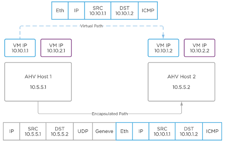
Flow leverages Geneve network encapsulation to provide Overlay networking allowing for creation of layer-2 segments without any changes to the underlay network. Each brAtlas bridge (and therefore each host) acts as a Geneve TEP. When two VMs on different hosts need to communicate, the host and bridge at the source will encapsulate the packet with Geneve, and the host and bridge at the destination will decapsulate and deliver it.
VLAN-Backed Networks
Flow can also manage VLAN-backed networks via the brAtlas bridge. This causes there to be a distinction between two types of VLAN-backed networks. The first is a VLAN Basic network. VLAN Basic networks are not managed by Flow. They are the standard AHV Subnets that exist on the virtual switch vs0 by way of the individual br0 bridges. This would include the management network used by AHV, the CVMs, and Prism Central. By default, VLAN-backed networks are created as VLAN Basic.
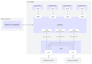
You can also create non-basic VLAN networks which are managed by Flow. In these instances, the VLAN is created on the brAtlas bridges. Each of these brAtlas VLANs is uplinked directly to br0 to provide access to the underlay. When a VLAN is create on brAtlas, a logical patch is created between brAtlas and br0 for that VLAN, as seen in the diagram.
A key to note is that by default, a VM cannot simultaneously be connected to overlay subnets AND VLAN-backed subnets. This limitation is put in place by Nutanix and can be overridden by Nutanix support if needed.
Flow Virtual Routing
Virtual Private Clouds
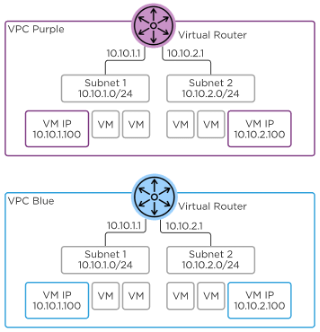
A Flow environment is comprised of one or more Virtual Private Clouds, or VPCs. A VPC can be thought of as an isolated network with a virtual router to connect all of the subnets inside the VPC, as well as provide egress out of the VPC. While VPCs can span multiple clusters managed by the same Prism Central, best practice states they should remain within a single cluster and should NEVER be extended outside of an availability zone. That is, no VPCs spanning clusters in two different markets. Overlay segments belong to a VPC and connect to the VPC virtual router1.
There are two types of VPC. The default type, often referred to simply as a VPC, can more specifically be thought of as Tenant VPC Nutanix recently introduced a second type of VPC, called a Transit VPC. Transit VPCs act as centralized north-south egress points for multiple VPCs, simplifying the interconnection to the underlay network. They can also facilitate cross-VPC communication, and host services intended to be used by multiple VPCs, such as Active Directory, File Services, or more.
As VPCs are isolated routing spaces, IP addresses can be overlap between VPCs, with NAT being used to facilitate communication between VPCs when IP overlap would otherwise prevent it.
The virtual router connects all of the subnets within the VPC and provides communication outside the VPC via an External Network. Traffic between two VMs in the same VPC, but in two different subnets, will be locally routed on that host. For external connectivity, one or more hosts is designated to handle logical routing for ingress, egress, and NAT. Each host assigned as the logical router responds to ARP requests for the router IP and floating (NAT) IPs. In the event of host failures or maintenance, the Network Controller will re-assign this to another host.
External Networks
Subnets can be specially purposed as external networks to provide external connectivity to a VPC. External networks can either be Flow-managed VLAN subnets or overlay subnets created in a Transit VPC. External networks can either be NAT or Routed (NoNAT) external networks. When defining an External network, you define the network and subnet mask, as well as the IP address of the gateway serving the subnet. You also configure an IP Pool out of which addresses will be assigned to VPCs connected to that external network.
NAT External Networks
A NAT External Network hides the private IPs of the VMs behind either a single VPC Source NAT (SNAT) IP, or behind Floating IPs. Floating IPs are assigned to VMs and act as 1:1 NATs. The SNAT and floating IPs are assigned out of the External Network’s IP pool.
Routed (NoNAT) External Networks
Routed external networks allow the IP space of the VPC to be exposed to and shared through routing. Traffic egressing the VPC via a routed network will not be NATed. As such, the VPC’s address space is no longer isolated from the address space outside the VPC, and IP overlap must be a concern. The Router IP becomes the next-hop address used by upstream devices for traffic destined for a routed subnet within a VPC.
Multiple External Networks
A VPC can have both a NAT and NoNAT External Network. This configuration should be used very intentionally, and the decision must be made which of the two paths is going to be the default path. That is, if your default path is the NAT External Network, you will need to specifically route traffic that you wish to not be subject to NAT to the NoNAT external network. Conversely, if you want traffic to be exposed by default, you will need to specifically route traffic you wish to hide to the NAT external network. This is accomplished via network policies, which we will discuss shortly.
The Nutanix Cloud Bible provides an example of how this might work for an organization that wants to NAT traffic that is destined for the internet, but leave internal traffic to physical infrastructure exposed. I personally dislike this particular design, and would strongly suggest the reverse, assuming that a perimeter firewall is in place external to the VPC.
Routes
Every VPC contains a single virtual router with a routing table. Directly Connected routes are created for each subnet inside the VPC. External Networks and Remote Connections (such as VPN connections) can be set as the next-hop destination for a network prefix. VPCs will typically have a default route of 0.0.0.0/0 pointing to an external network, but this is not required.
Network Policies
Simple stateless policies can be applied to any traffic that flows through the virtual router. As these policies are stateless, any specific policy must be applied in both directions to work as expected. Policies are configured like traditional access control entries, with a source, destination, port, protocol, and action. The action options are Allow, Deny, Reroute, or Forward. Policies are assigned a priority between 1 and 1000 and are processed in order from highest to lowest. Priorities must be unique. Therefore, a single VPC is limited to 1000 network policies.
Allow and deny policies are useful for controlling traffic between segments or at VPC ingress/egress. Being applied at the virtual router, they cannot be used to control traffic within a segment, as. As stateless policies, they must be configured bi-directionally. That is, for an allow rule to override a drop rule, both forward AND reverse traffic must be explicitly allowed. An unchangeable “deny all” rule is configured by default. A higher-priority “allow all” rule is also configured by default, but this is a changeable/removable policy.
Reroute policies allow traffic to be redirected to another VM within the VPC, specifically intended network function VMs such as load balancers or firewalls. For instance, web servers can have outbound traffic forwarded to a load balancer.
Forward policies enable source- and/or destination-based routing to alternate external destinations2. For example, while a normal static route can cause traffic intended for VPN destinations to be routed to a specific VPN firewall, a forward policy that make that routing decision based on source, port, and protocol, as opposed to just the destination network.
Network Gateways
Certain stateful services, for providing external connectivity such as BGP, VPN, and VXLAN Bridging, require the deployment of service VMs. These VMs will be deployed by Prism Central using images fetched from Nutanix. These service VMs that these gateway services run on utilize VyOS, a Debian-based Linux specially built for network functionality.
BGP Gateways
BGP gateways facilitate the exchange of routing information between a VPC and an external BGP peer. They do this outside of the data plane by way of a BGP Speaker in the control plane. The BGP Gateway can be placed on either a VLAN or Overlay network. Placing the BGP on a VLAN gateway greatly simplifies this by avoiding the need for a floating IP, and is therefore strongly recommended.
The BGP Gateway forms a BGP peering and advertises VPC networks identified as externally routable. However, it advertises them with the next hop not being itself, but instead being the VPC router IP. This process of existing only to announce routes while not itself participating in the data path is why it is referred to as a BGP Speaker.
Any routes learned by the BGP Gateway will be added to the associated VPC router table with the NoNAT External Network as the next-hop. BGP gateways are configured with the same number of router IPs as the VPC they are serving. That is, if the VPC is configured with two active hosts, the BGP Gateway will have two IPs to build BGP sessions from. Each IP will advertise one of the VPC router IPs as the next hop.
VTEP Gateways
VTEP Gateways provide cross-cluster subnet extension capabilities by way of VXLAN encapsulation. Subnet extension allows for subnets in different availability zones (that is, remote clusters) that share the same network prefixes to be joined via VXLAN. The primary use case for this is to allow workloads that are migrating as part of a disaster recovery event to keep their same internal IP scheme without the use of NATs while still allowing the production and disaster recovery environments to be on-net with each other by deploying VTEP Gateways in both clusters.
The VTEP Gateway is deployed on a special services network within the VPC that is automatically created when the first gateway is deployed, called Nutanix-vpn-internal which will use the 100.64.1.0/24 address space. The VTEP Gateway will then have an interface in the subnet to be extended, with a ‘listener IP.’ Any MAC addresses observed by the listener IP will be flooded to the VXLAN gateway on the remote side. The listener IP will pick up any traffic destined for a MAC address learned from the remote side and forward it to the remote side.
VTEP gateways can also be used to bridge a subnet to a VXLAN VTEP on physical infrastructure, including Cisco, Arista, Juniper, or any other standards-compliant VXLAN VTEP.
Subnet extensions created by VTEP gateways should not cause one to freely utilize both sides of the extension for active workloads. They should be treated as a tool to assist in disaster recovery or workload migrations.
VPN Gateways
VPN Gateways are VMs that can be instantiated to build IPSEC VPNs to bridge layer 3 domains. While most organizations would likely leverage a proper firewall as the termination point for VPN tunnels (and in fact I’d strongly recommend that VPN tunnels be terminated on a firewall), this capability can be found in Flow. More information about VPN gateways, should you be interested, can be found in the Flow Virtual Networking section of the Nutanix Cloud Bible.
Firewall Placement Considerations
Many organizations today choose to leverage VM-based firewalls, as they are quite often just as capable as their physical brethren. However, there are some design requirements in Nutanix that we’ve already discussed which will require additional planning before implementing a VM-based firewall.
The first is simply that an External Network cannot be attached to the vNIC of a VM. Consider the following very beautiful diagram:
( Internet ) <—> ( Firewall ) <—> ( VPC )
This is the immediate obvious way that one might deploy a firewall in front of a Nutanix VPC. However, we immediately run into an issue when trying to connect the inside of the firewall to the VPC as an external network. That issue is, simply, that you can’t do that. An external network cannot be used as anything other than an external network; it cannot be attached to the vNIC of a VM-based firewall.
There are two ways main ways to solve this issue, although I’m sure some clever individual has others. The first is to have a separate edge/management cluster which uses exclusively VLAN-backed networking, and have your firewall (and Prism Central, or any other management VMs you so choose) there. In larger-scale deployments this idea of a distinct management cluster is, in fact, a Very Good Idea™.
The second way to solve the issue would be to leverage a transit VPC and place the VM-firewall there. Network policies would enable traffic from tenant VPCs to be rerouted through the VM firewalls before egressing the transit VPC to the internet.
If you are leveraging a physical firewall platform, this is a non-issue! Carry on!
In the next section, we’ll cover securing a Nutanix environment with Flow Network Security.
